Three-Dimensional Modelling of Historical Underground Workings
The mining industry mostly embraced digital technology, but many historical mines still have huge paper data archives. Converting these paper maps into a digital, preferably three-dimensional format is a challenging but necessary for making this information available for modern mine design, planning and support technologies.
A typical workflow for converting a drawings into a 3D model includes the following steps:
- Scan, enhance and clean up the scanned image
- Georeference
- Vectorise (or digitise)
- 3-D modelling
- Integration of three-dimensional underground workings into the general model of the deposit
Scaning
Modern large-format scanners allow to digitise of a scanned copy of a map on a computer monitor. The optimal ratio of resolution to file size is very significant for scanning. The resolution should be sufficient to clearly show the smallest important objects, but not too high, which leads to large files and slows down further work. The standard resolution is 300 dpi, but sometimes it needs to be increased depending on the detail and quality of the paper map.
Better to use file formats that do not result in a loss of image quality, such as uncompressed formats like TIFF or BMP, or compressed formats like PNG. The use of JPEG, for example, requires attention to quality loss.
If the map is clean and contains single-colour line drawings, then a black-and-white (1-bit) or greyscale (8-bit) scan is ideal. But if it contains coloured linework or filled polygons, then you’ll need to do a true colour (24-bit) scan using RGB or SMYK colour models.
Photo editing software is commonly used to enhance and clean up images, with special automatic and manual correction and editing tools.

Georeferencing
To georeference a raster image, you should set control points with defined coordinates and specify a coordinate system. The basics of working with coordinate systems are described here.
Coordinate reference points (control points) should be placed as close to the image perimeter as possible, and their number depends on the image quality, the degree of image distortion or deformation.
A relatively fresh, well-preserved and well-scanned map may require a limited number of control points. If the map has been affected by time or if the image is distorted by scanning, more control points will be required.

Vectorising (or digitising)
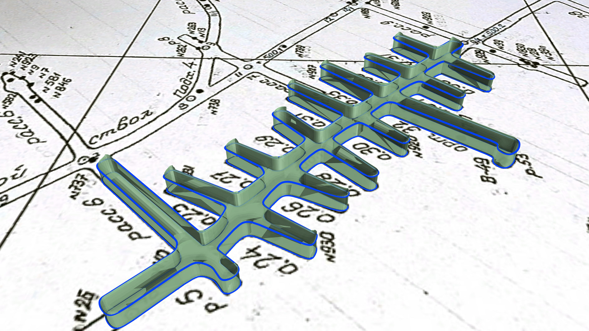
To convert a paper image into a 3D model, the required objects must be digitised or vectorised. In the case of underground mine workings, these objects are the sidewall contours or centerlines of the mine workings.
Most commonly, digitisation (vectorisation) is performed in plan view with automatic assignment of X and Y coordinates. However, all 2D data must be converted to 3D before it can be used to create underground working wireframes.
The following are some ways to assign elevations:
- assigning the same Z coordinate to all horizon objects,
- assigning elevations in the process of digitisation, if relevant data are available,
- projection of digitised objects onto the DEM (digital surface model) of the corresponding horizon.

3-D modelling of underground workings
The process of creating a three-dimensional model of an underground workings depends primarily on the available source data, such as sidewall contours, centrelines or sections. Micromine Beyond has a wide range of tools for underground mine design that allow to convert lines into wireframes, namely:
- “Centreline to solid” – build the underground working solid based on the centreline and profile shape.
- “Sidewall to solid” – build the underground working solid based on the polygonal line of the sidewalls and profile shape.
- “Tunnel to Centreline” – generate of centreline of a working represented by sidewall lines or a solid
- “Sidewall Centreline Offsets” – Calculate left and right offsets from an input centreline and sidewall lines
- “Floof + Roof to Solid” – generate a solid from points or lines on the sidewalls of the floor and roof
- “Floor Wireframe” – generate floor wireframe from the lines and/or points


1. From sidewalls
In case historical paper level plans contain sidewall lines of underground workings, it can be used to build three-dimensional workings by specifying the profile shape parameters.

2. From centre lines
For more accurate display of underground workings in the form of wireframes, centre lines can be additionally prepared using the tools for smoothing, simplifying and/or regularising points. Choosing the tools and their parameters, keep in mind that each line segment will be converted into a corresponding workings segment. If required, centrelines can be generated from the side walls.

Based on the centreline, you can create an underground working wireframe according to the specified profile parameters, such as parameters: Width (X), Height (Y), Top (T)/Bottom (B), X offset, Y offset, Top corner / Bottom corner radius.
 3. From sections
Historical data can be represented by more accurate mine surveying constructions, such as intersections with profile shapes along the workings. In this case, the intersection lines can be digitised (or drawn) and used to build a mine wireframe by standard wireframe modelling tools.

Three-dimensional models of historical mine workings can be used for further mine design and planning. Spatial visualisation of workings allows an accurate assessment of ore body accessibility, logistics and the design of new workings based on the geometry of existing ones.

Combination with geological exploration data (drill holes and channel samples) allows more accurate reconstruction of the ore body geometry. In some cases, the comparison of underground workings and the block model of the deposit allows to determine the volume of historical production and residual resources.

Models can be exported in different formats (e.g. .DXF, .OBJ, .DWG, etc.) for use in CAD or GIS environments, for sharing between specialists and teams. Such data can also be used in reporting and technical documentation, including for mine designs, resource estimation, mining scheduling, etc.